Energy Management System Upgrade
Adding an Energy Management System and
Upgrading the Wardrobe on Our 2007 Allegro Bus
Article Date: January, 2013
Article and Photography by Mark Quasius
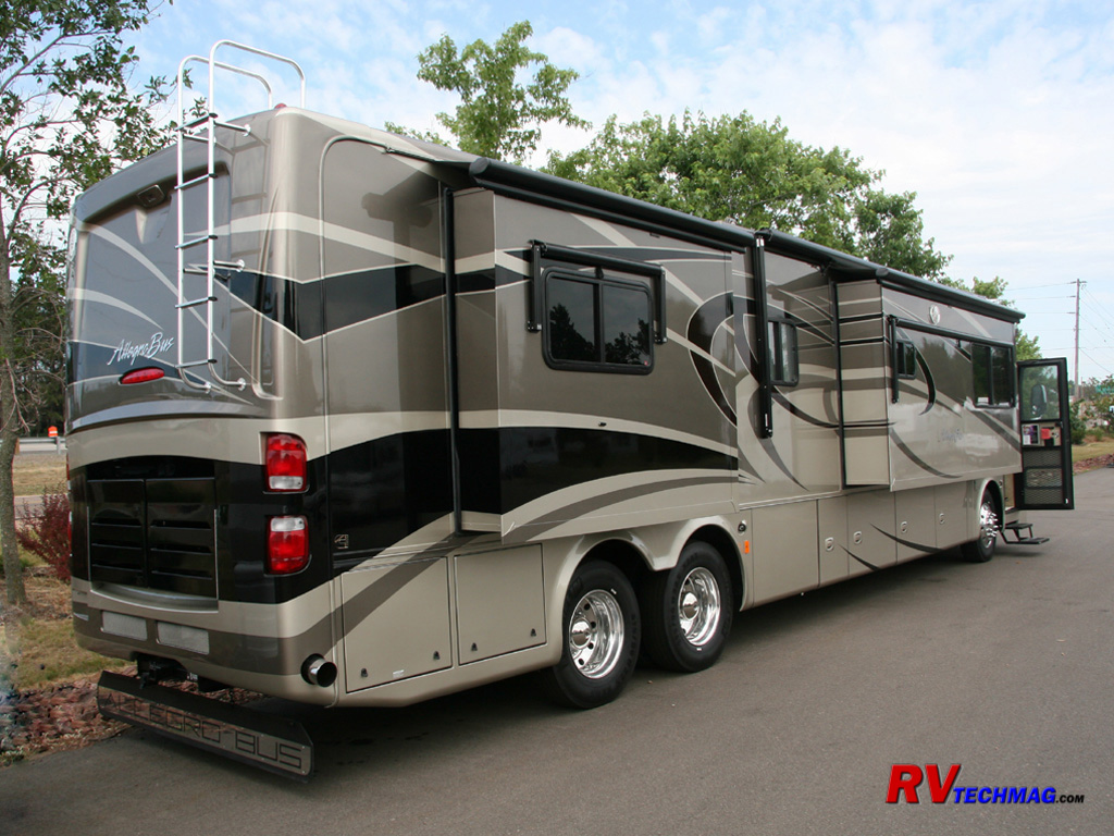
When we first purchased our 2007 Allegro Bus 42QRP we found one area that didn't quite suit us. The original design
contained a large vertical cabinet enclosure that contained the various electrical panels. It was a total waste of valuable wardrobe space and we
also wanted a load shedding energy management system that would eliminate having to reset any tripped pedestal breakers when on a 30 amp shore power
service. Before even took delivery we had our dealer, Kings Campers remodel this cabinet
according to my design. I then installed an Intellitec breaker panel that featured an Energy Management System. This served it's purpose for the
time but a number of recent changes have taken place that encouraged me to take this to a new level and create a Stage II upgrade project.
The original design was based around the Intellitec EMS-800 panel, which was quite large. The new 2010 Allegro Bus and Zephyr
came out with a new breaker panel design that incorporated an EMS system. This was a compact system that featured a more technically advanced EMS
system than the Intellitec system. The smaller size allowed me to relocate the breaker panel and reclaim some more of my wardrobe area. At the same
time I wanted to install an overhead shelf and now that the half-height cabinet could be removed, this would be practical. Plus, I was itching to
improve something on my RV because it's been a while since I did any really cool projects to it  . .
So, I embarked upon a new project. I obtained the new breaker panel and EMS system from
Precision Circuits, Inc. and laid out a plan on how to achieve all of these goals.
The end result was that I was able to totally remove the existing cabinet, relocate the electrical panel into a recessed floor area, add a full-width
overhead shelf in the wardrobe, and repanel everything to look as if it came that way from the factory. I've documented the details in my tutorial
below.
The Existing "Phase I" Situation
The coach was originally outfitted with a tall electrical closet in the right half
of the wardrobe that ate up a large portion
of valuable storage space. I decided to modify this to gain some room and add an energy management system.
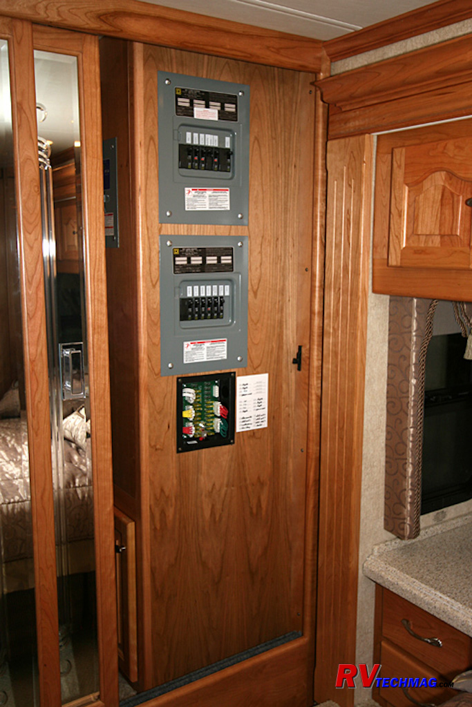
Original Wardrobe
Our initial modifications removed the top half of the cabinet, which is visible in the right side of the open wardrobe closet.
While this was an improvement in that it offered the ability to hang shirts above the new enclosure it did not offer full height storage in that area
nor did it offer any access to the closet center area from that side.
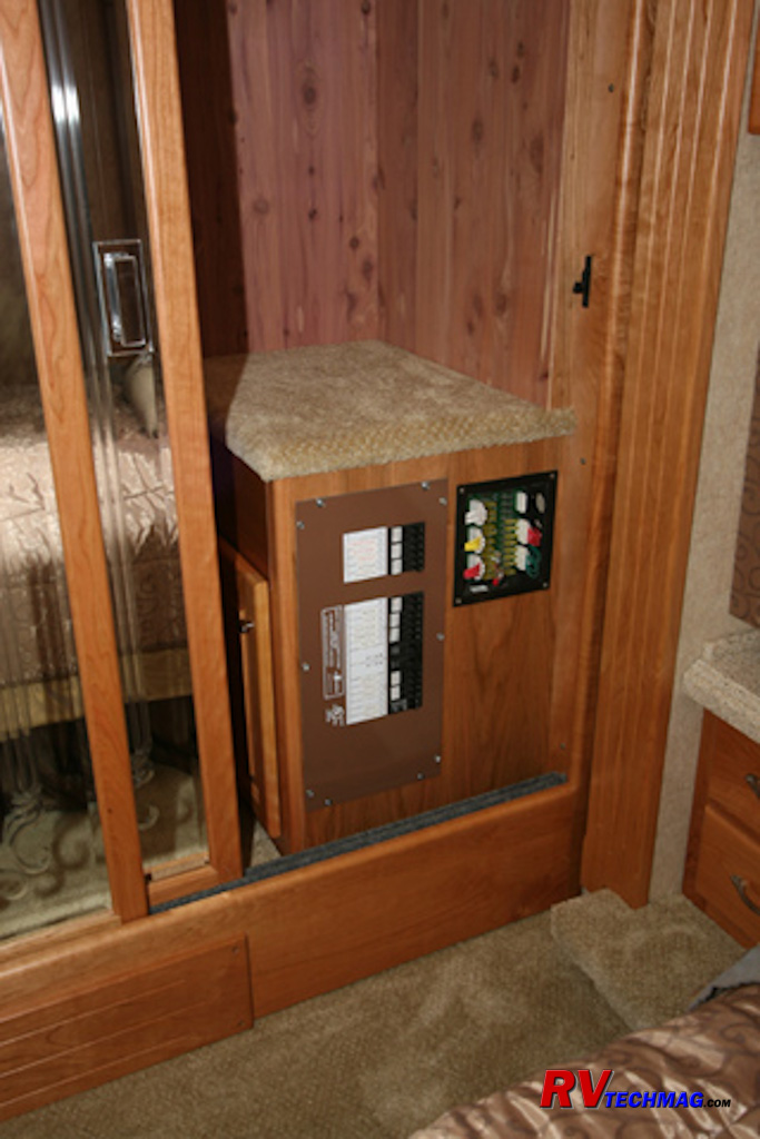
The left image shows a close-up view of the cabinet. The 12 volt fuse panel was retained in this location and the Intellitec
breaker panel was also located in this enclosure. The large width of the panel meant that it needed to be oriented vertically because the cabinet
wasn't wide enough to allow horizontal placement. A carpeted top was placed on the cabinet to cap it off and serve as a shelf.
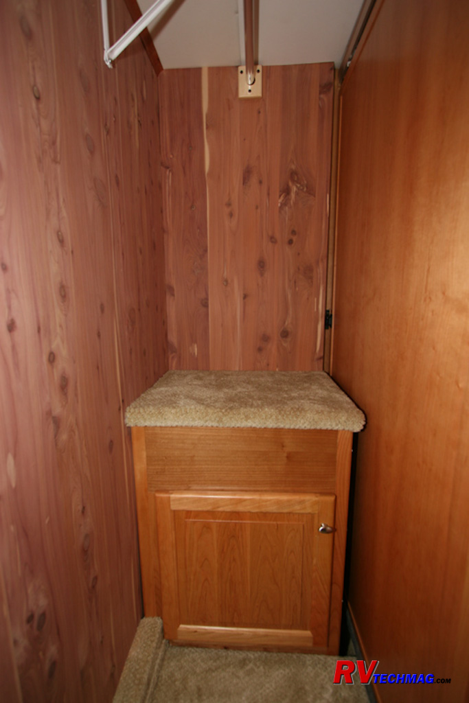
The right side image shows the cabinet as viewed from the opposite end of the wardrobe. There was a hardwood cherry door that
allowed access to the cabinet but the maze of wiring inside the cabinet meant that it really served no practical function. However, it was there as
delivered from the factory so there was no sense in removing it.
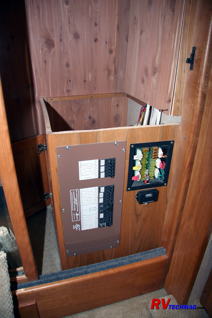
With the top removed it's easier to understand the sidewall configuration. When the original cabinet was cut down to half-height
the various wiring runs, that passed to the ceiling were left exposed. The tech at Kings Campers located them alongside the side wall and fired it out,
then covered that area with a short piece of cedar paneling to match the rest of the wardrobe. Once this cabinet is removed the sidewall panel will need
to be extended to the floor area.
The New "Phase II" Plan
My plan was to remove the cabinet entirely. That cabinet actually sits into a well that extends beneath the closet floor by about
a foot. The new PCI breaker panel would easily fit in that well and the 12 volt fuse panel could easily fit into the closet side wall. A carpeted floor
panel would cover the recessed breaker panel. Technically this would make it a bit harder to access the circuit breakers. I would have to lift up the
floor panel, after removing any shoes or whatever that were resting in that spot. However, it doesn't take more than 30 seconds to do that and quite
frankly I can't remember the last time I ever tripped a breaker on my coach. So, it really was a practical solution. The deep well was dead space anyway
and by utilizing it for the breaker panel I reclaimed some valuable storage space in the wardrobe.
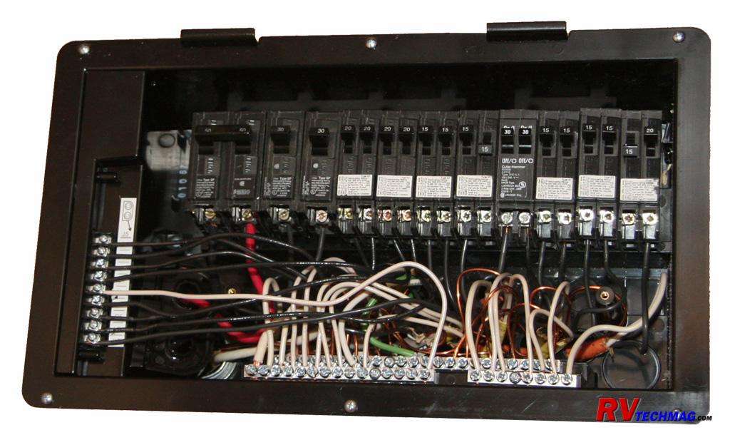
PCI Breaker Panel Assembly
The Precision Circuits, Inc (PCI) panel was not only smaller, but a much higher tech design. The Intellitec system was good and
it did its job but it wasn't as sophisticated as the PCI design. The Intellitec system samples voltage at both L1 and L2 and monitors current flow
through the neutral wire. If it sees 240 volts across L1 and L2 it knows that you are on a 50 amp shore power feed so it does nothing. If it does not
see 240 volts it knows you are not on a 50 amp service. It then tests to see if it has 12 volts present on the generator run wire. If it sees 12 volts
it knows you are running on the generator and still will not shed any loads. It will display the generator amperage on the meter however. If no 12 volts
is present it knows you're on a 30 amp shore power feed. In that case it will shed circuits according to your pre-configured load shedding order in
order to keep the total current draw beneath 30 amps so that your pedestal breaker will not trip.
Now, this system works well enough, but it does have its shortcomings. First of all it only samples current on the neutral wire.
Therefore it does not have the capability of displaying how much power you are using when on a 50 amp shore power feed or even if you are running a
120/240 volt generator, such as the Onan 10,000 watt or larger. It also does not shed any loads when on generator power. Still, it does its job of load
shedding effectively.
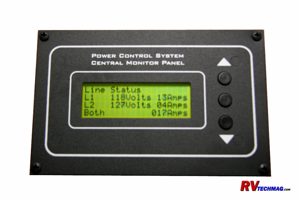
PCI Remote Display
The PCI system takes it up another notch. In addition to more sophisticated software it offer the ability to customize the
system via a laptop computer, whereas the Intellitec system is configured using DIP switches on the circuit board. The PCI system has dual current
transformers, one on L1 and one on L2, so it can report both voltage and amperage under any and all conditions. It also handles energy management
operations when running on your generator so that tripped generator breakers are now a thing of the past. The LCD display provides full featured
readouts of both voltage and amperage as well as numerous other parameters. It's much more informative than the Intellitec system and serves well
as an energy monitoring station.
A real boon to the PCI system is the ability to communicate with a Magnum inverter. Normally, whenever you are running on a
30 amp shore power feed and you draw more current than is available the only recourse for an EMS is to shed loads to keep the total system draw to
less than 30 amps. The PCI system will communicate with a Magnum inverter and will switch on the inverter first. If that provides enough power, it
won't have to shed any loads. If you power needs are still in excess it will then shed loads as a second stage action. If the inverter remains on
for an extended length of time the EMS will switch it off and simply shed loads.
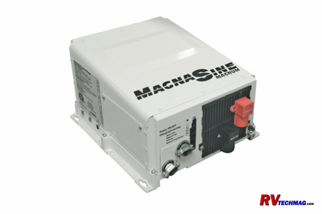
Magnum Inverter
Typically what happens is that your coach is running an air conditioner or two when someone wants to use a hair dryer, switch
on the microwave for a minute or two, etc. In this situation the EMS will switch on the inverter to power the new temporary loads and then switch it
off once those loads have been removed. This means that your air conditioners can continue to operate instead of being shut down for that period of
time. Note that in order for this to happen, you must have a Magnum inverter. The PCI EMS does not communicate with a Xantrex inverter.
The PCI panel features all of the electronics incorporated within the panel box. Four AC circuits can be controlled as well
as three DC circuits. The DC circuits can be used to control air conditioner thermostats, engine block heater relays, hot water heater relays, etc.
PCI also makes DC powered relays that control AC circuits so in reality you can have up to seven AC circuits to shed loads from. The remote display
panel is connected to the breaker panel via a modular phone wire connection and you also need to provide 12 volt connections to battery, ground, and
the generator hourmeter. Detailed information on installing the PCI EMS can be found at the following links:
This is a nice design and it gave me the ability to reclaim some space as well as upgrade my technology at the same time.
Unfortunately, I still had a Xantrex RS3000 inverter which produces clean true sine wave power and is in good working condition. I could not justify
throwing it out just to gain the extra benefits the PCI system offers with its inverter interface at this time. So, I kept my Xantrex inverter initially
but later on upgraded to a Magnum MSH3012 Hybrid Inverter later on. That article can be found at This Link.
Performing the Modifications
Once I had drawn out my plans for this project and obtained the materials needed it was time to begin the project. The initial
step was to remove the existing cabinet, strip out any unnecessary woodwork, and trim down the existing wiring to make it more manageable.
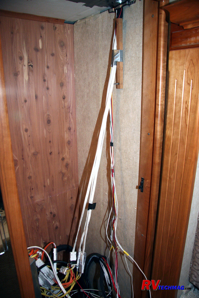
The existing cabinet was fastened to the floor of the well in that area. I needed to pretty much disassemble the enclosure,
which was held together via screws for the most part, in order to remove it. I also removed the cedar paneling that covered the top half of the side
wall to hide the electrical wiring run to the ceiling. This image shows that area once the cabinet was removed. as you can see, the wiring was too
short to reach fully into the floor well so I disconnected the 120 volt wiring at the modular connectors and made extension lines to the floor well
area to connect to the PCI breaker panel. I did not need to lengthen the 12 volt wiring because I planned on locating the 12 volt fuse block in the
new sidewall enclosure.
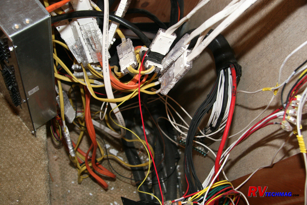
As you can see there was lots of unorganized wiring within the floor well. Much of it was longer than needed because it needed
to reach upwards into a full height cabinet. The wiring that came down from the ceiling was now too short because it never had to reach fully into the
floor well area.
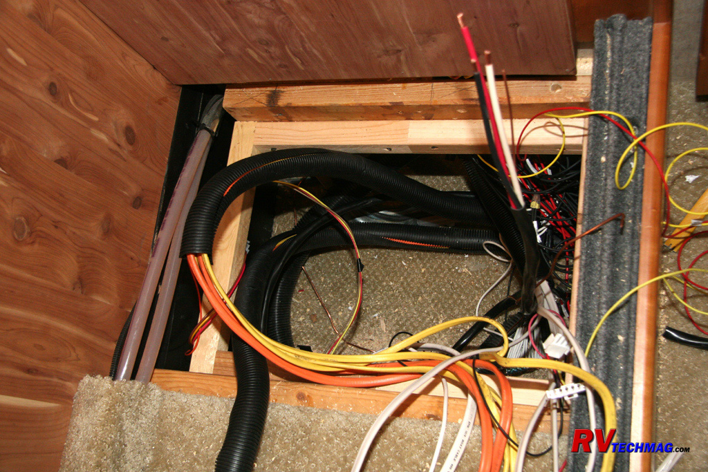
At this point I extended the sidewall wiring to the appropriate length. I then furred out the area, clamped the wiring harnesses
to the sidewall, and added a new cedar panel to fully enclose the sidewall wiring. I then trimmed down the excessive length wiring in the floor well
and built a wooden frame structure to support a new panel that the breaker panel would mount to. This panel was to be recessed beneath the wardrobe
floor so a double step design was needed. The lower step was to support the breaker panel and enclose the wiring beneath it while the upper step was to
support a carpeted wardrobe floor capable of supporting a
person's weight.
This view shows the double stepped support frame to accomplish this, as well as some of the trimmed wiring, although that task
was not fully completed when this photo was taken. You can also see two coolant lines that supply the Hydro-Hot heat exchanger at the far side of the
wardrobe. These lines were run laterally across the back of the wardrobe in a carpeted ledge above the wardrobe flooring. The portion visible in this
photo was originally hidden by the cabinet, which is now gone. I needed to create a new carpeted ledge to extend across the remaining area. This ledge
also served as a place to tuck the new carpeted floor panel beneath it for a tighter looking fit.
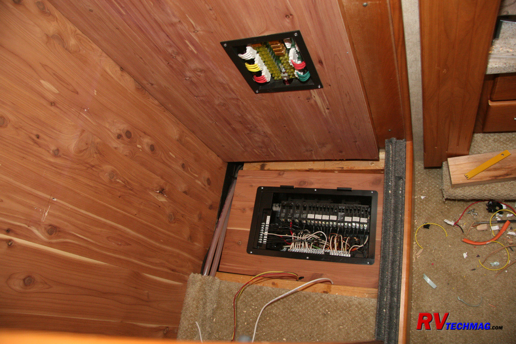
This view shows the 12 volt fuse panel as installed in the new cedar paneled sidewall. It also shows the breaker panel being
installed into the sub-floor panel, which was also made from a cedar paneling cutoff. Once the wiring is completed the panel will drop down beneath
the 2x4s that can be seen and the breaker panel cover will be installed. Next the carpeted ledge to hide the Hydro-Hot lines will be added and a
carpeted flooring insert will be fitted into place.
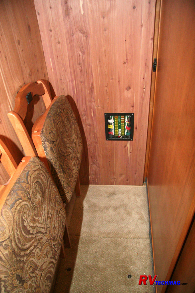
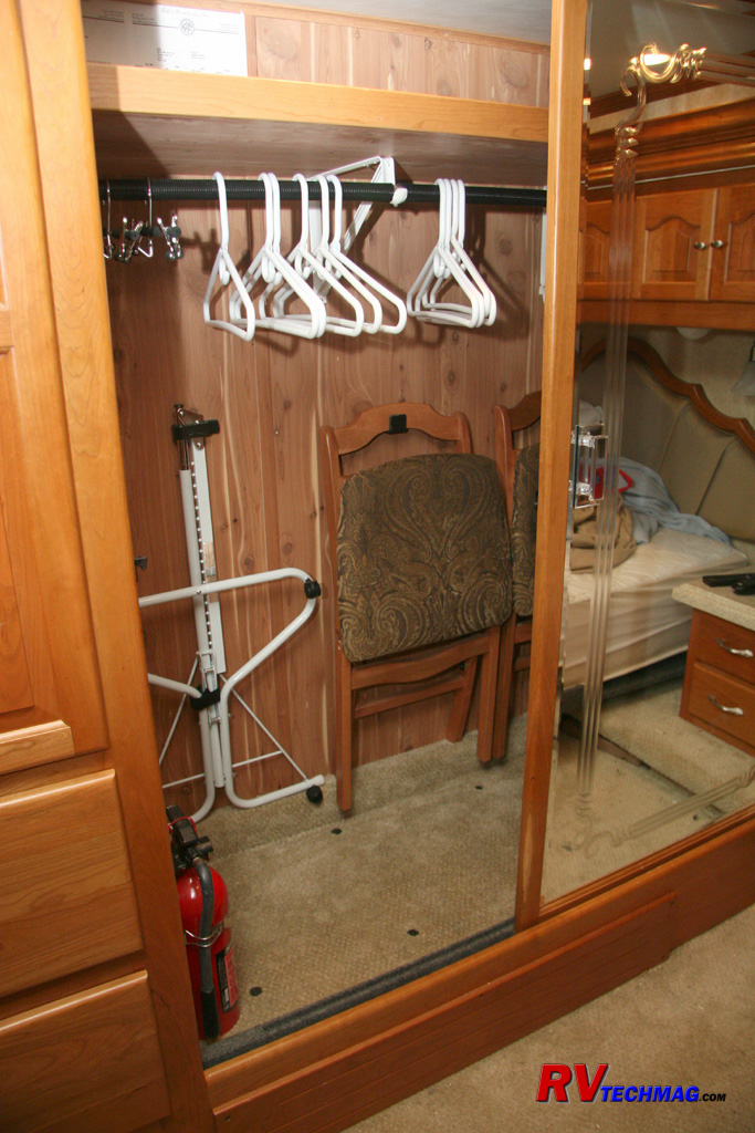
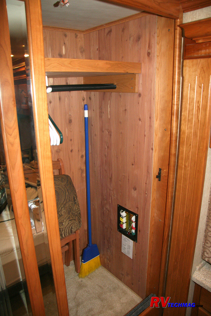
The finished wardrobe floor now has a carpeted panel. A finger hole was placed into the carpeted floor panel to facilitate
easy removal of the floor panel should it be necessary to access the breaker panel. The two folding dinette chairs are resting on the carpeted ledge
that covers the Hydro-Hot lines running across the back of the wardrobe. Flat metal hooks were made and lined with the fuzzy part of Velcro to hold
them up. These chairs can remain in place if the breaker panel ever needs to be accessed.
|
|
|
Now that the sidewall, and wardrobe flooring were complete it was time to look up to the ceiling. The original ceiling had a
large chunk cut out of it in order to drop the overhead wiring into the cabinet. A white patch panel had originally been placed there to cover that
hole. However, I wanted to improve on that so I ordered some new ceiling headliner from Tiffin and made a new 1/4" panel to overlay over the existing
ceiling. The foam backed headliner was stretched over that panel and stapled in place on the backside of the plywood and the panel was lifted and
fastened in place.
Finally, I added an overhead shelf to span the entire width of the wardrobe. I added a lip to the front of the shelf, carpeted
the top to minimize cargo movement, and even added a piece of aromatic red cedar paneling to the bottom because I had some left over and it was easier
than staining and refinishing the plywood. The clothes pole was lowered accordingly and there's plenty of room to hang clothing while still gaining the
usefulness of the overhead shelf.
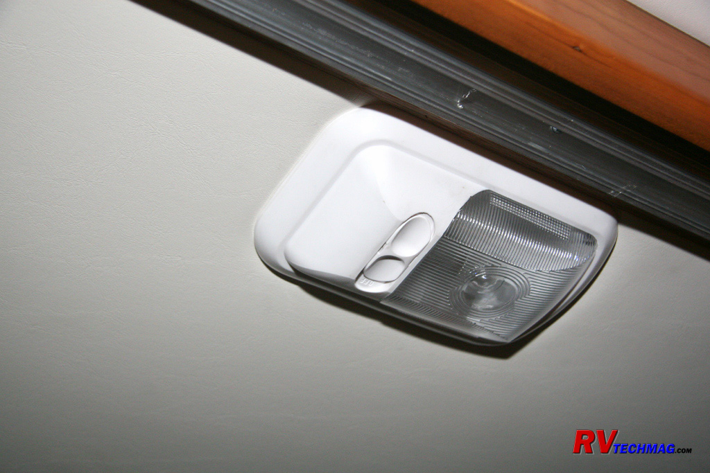
Now that I had full use of the entire width of the wardrobe I decided that some additional lighting would be handy on the right
side. I extended the wiring from the existing wardrobe light on the left side of the ceiling and added a second overhead light on the right side. I
thought about automating them so that they turn on whenever the wardrobe doors are open but we don't tend to close them all the time so decided that
they would be best off staying as manually operated.
Summary
This turned out to be a very helpful upgrade. While the existing Intellitec EMS system was a decent system, the Precision
Circuits EMS system was of much newer technology and offered some nice new features. In itself, it would be harder to justify upgrading from a good
EMS system to a better one but with all of the additional benefits that would occur by this upgrade it was worth it. The smaller size of the panel
was a huge factor in making this decision. It let us recover a sizeable amount of accessible wardrobe storage that was previously not available. At
the same time it allowed us to gain that overhead shelf, resulting in even more storage. Upgrading from the Xantrex RS3000 inverter to a Magnum MSH3012
gave us additional energy management capabilities as well as an inverter that is American made and field serviceable, unlike the Xantrex. I was even
able to save the hardwood cabinet door from the existing cabinet and incorporate it into a new cabinet that I built that is now located in the bathroom
area directly over the water closet. All in all this was a very productive upgrade.
Return to Home Page
If you enjoyed this article be sure to recommend RVtechMag.com to your friends, like us on Facebook or Twitter
or subscribe to our RSS feed.


|


