Hydro-Hot System Upgrades
Upgrading the Hydronic Heating System on our 2007 Allegro Bus
Article Date: April, 2008
Article and Photography by Mark Quasius
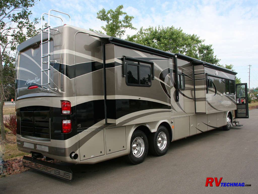
The 42' Allegro Bus utilizes hydronic heating in the 42', which is also optional in the 40' coaches. My 2007 42QRP came with
the Hydro-Hot system, manufactured by Vehicle Specialties. In the 2008 model year Vehicle Systems underwent a name change to Aqua-Hot Heating Systems
and the Hydro-Hot name was replace with Aqua-Hot. However the units are virtually the same so any pertinent data is identical between them. For more
information on both hydronic heating systems please check out this reference in the
RV Tech Library.
Tiffin did an excellent job when the designed the 42' tag axle coaches. Normally, adding a tag axle reduces the basement
storage space by 4' in order to allow for the room taken up by the extra tire and fender well. When Tiffin Motorhomes designed the 42' Allegro Bus
they eliminated the dual propane furnaces and hot water heater and went with the Hydro-Hot as standard equipment. By locating this unit in the center
of the coach in a smaller compartment they were able to retain much of the basement space given up to the tag axle. The net result was that my 2007
42' Allegro Bus had pretty much the same useable basement storage space as my 2004 40' Allegro Bus. The downside to this was that the Hydro-Hot was
pretty much buried and hard to get to. Seeing as how it does require an annual service, this does complicate things. Because I service my own coach
I decided to make things easier so I did a few modifications to accomplish this. They are detailed below.
The Situation
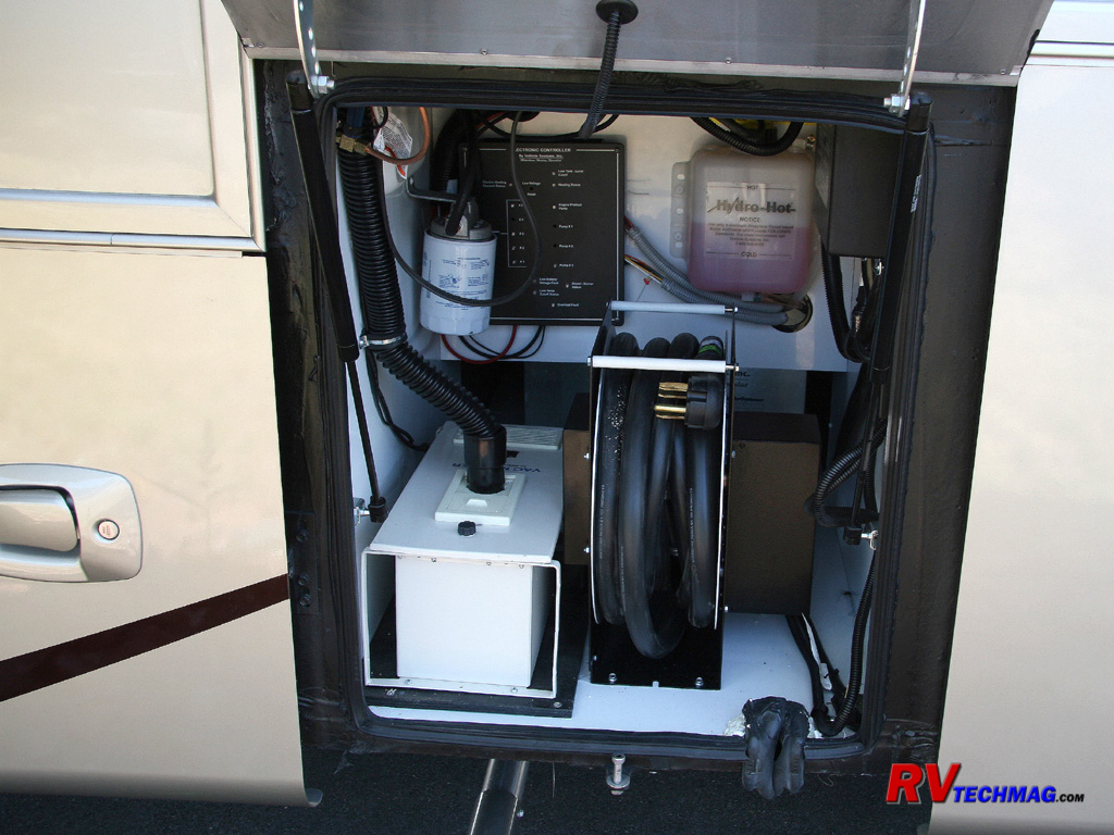
This shot of the original electrical compartment shows the clutter of that area. To the very left is the white VacMaster
central vacuum system. Immediately to its right is the power cord reel. On the back wall, a white coated plywood board is used to mount the Hydro-Hot
antifreeze surge tank/reservoir as well as the black electronic controller panel for the Hydro-Hot. The fuel filter for the Hydro-Hot is also mounted
on the left side wall. One other issue, not visible here, is the hour meter for the Hydro-Hot's diesel burner. This is located on the top of the boiler,
and is virtually impossible to see.
In order to perform the annual burner service, you need to remove the power cord reel and the central vacuum. Then you have to
crawl into the compartment and try to remove the sheet metal cover on the boiler. Aggravating this is the fact that the white panel is very deep and
masks the top half of the boiler from view. In order to remove the boiler access cover, the white panel really needs to be unfastened in order to
shift it. Once the boiler is accessible you can see the hour meter if you lay on your back and shine a light on the top and use a mirror.
I also needed a place to mount my Progressive Industries EMS HW 50C surge suppressor that needed to be mounted someplace and
I also had a Hughes Autoformer to boost voltage whenever the campground's shore power was marginal. I wanted to place that inside the compartment
where it was safe and out of the weather rather than outside.
Lastly, we weren't impressed with the performance of the VacMaster central vacuum and much preferred the Dirt Devil, which we
had on our previous RV. So I ordered a Dirt Devil and created a plan to change everything. Many of these ideas were a composite of things I've learned
from other members on the Tiffin RV Network forum. I just put them all together, added a
few of my own, and went to work.
The Solution
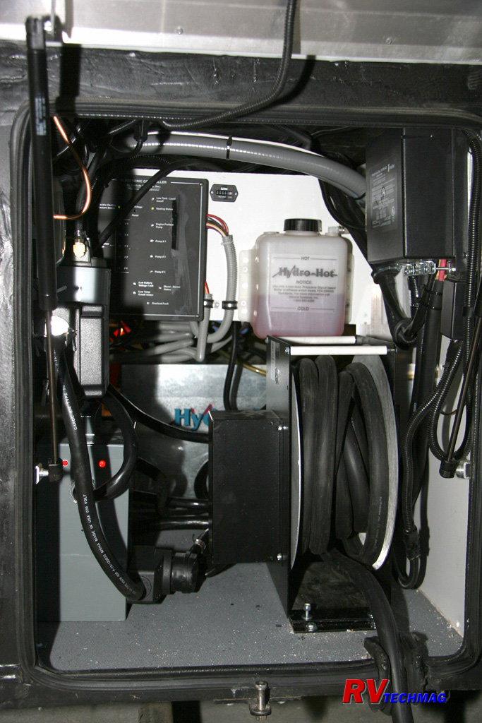
This image shows the compartment after my modifications were done. I began by removing the VacMaster central vacuum. I then
placed my Dirt Devil vacuum in the main basement compartment, on the wall immediately adjacent to the original VacMaster's location. Basically I just
moved it to the other side of the wall. It was an easy task to simply move the hose and wiring over to the other side by using a hole saw to make an
opening between the two compartments and dropping the hose and wires down to the other side. I was able to retain the existing hose and wiring and only
needed to swap the main units. I mounted the Dirt Devil up high, next to the frame rails so that it did not intrude on any basement cargo space.
I then mounted my surge protector on the left side wall, keeping it high enough to allow room to place my Autoformer directly
underneath. The cord reel was located closer to the wall and I now had room to place misc accessories.
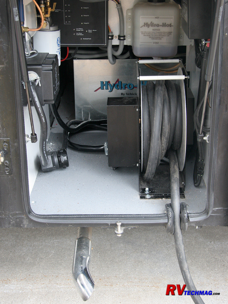
Next I came up with a quick release system for the power cord reel. I installed a weatherproof quick disconnect fitting on the
12 volt wires that operate the cord reel's rewind motor. I also installed a large 50 amp 4 wire plug and cord end on the output side of the cord reel
so that I could disconnect its output from the surge suppressor. It also gave me an insert point to plug the Autoformer in if I needed it. I then
fabricated a set of quick release mounting plates for the cord reel that allow it to slide and lock into place. By simply removing two nuts, unplugging
the 50 amp output, and unplugging the 12 volt terminal coupling I can remove the power cord reel within 2 minutes. The cord connection also gives me an
insert point to connect the Autoformer should I need it. The Autoformer simply lifts right out and now I have a completely open floor space. To top it
off I lined the compartment with 3M Safety Walk material.
The next step was to remove the Hydro-Hot's antifreeze reservoir bottle and controller from the back panel and take the panel
out. I then sawed off the bottom 8" or so from the panel so that I could actually get to the Hydro-Hot boiler. I then mounted the reservoir in the exact
same place and raised the controller panel up to align with the new, shorter panel. The end result was that I could now easily remove the steel access
cover from the boiler to get to the burner assembly without ever having to bother with the whiteboard panel. It's now a 5 minute job to expose the
burner for any service work.
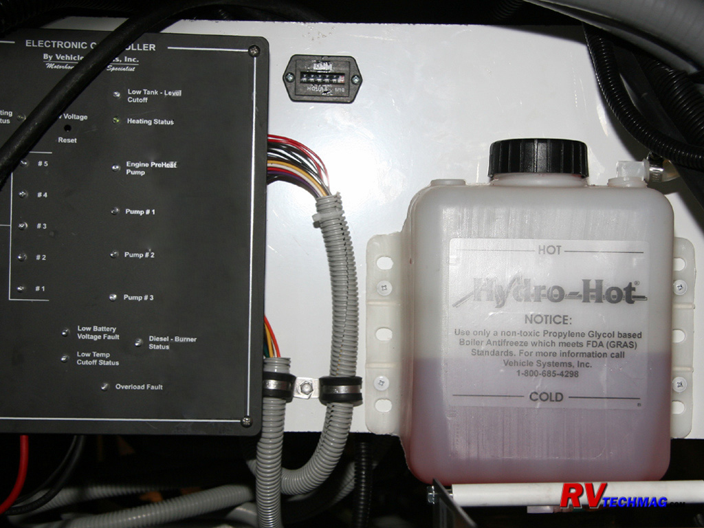
This close-up shows the new hour meter location. Because the existing hour meter was virtually impossible to get to, I bought a
new one and mounted it into the panel. I simply removed the wires to the OEM meter and ran them to the new meter by running wiring loom through the
access hole in the top of the boiler. The OEM meter was riveted to the boiler and would have been a project to try to drill it out given the confined
space, so I just left it and added a new hour meter. Sorry for the antifreeze smear on the controller cover. I took the picture before I had a chance
to clean it off and the flash reflected in it badly.
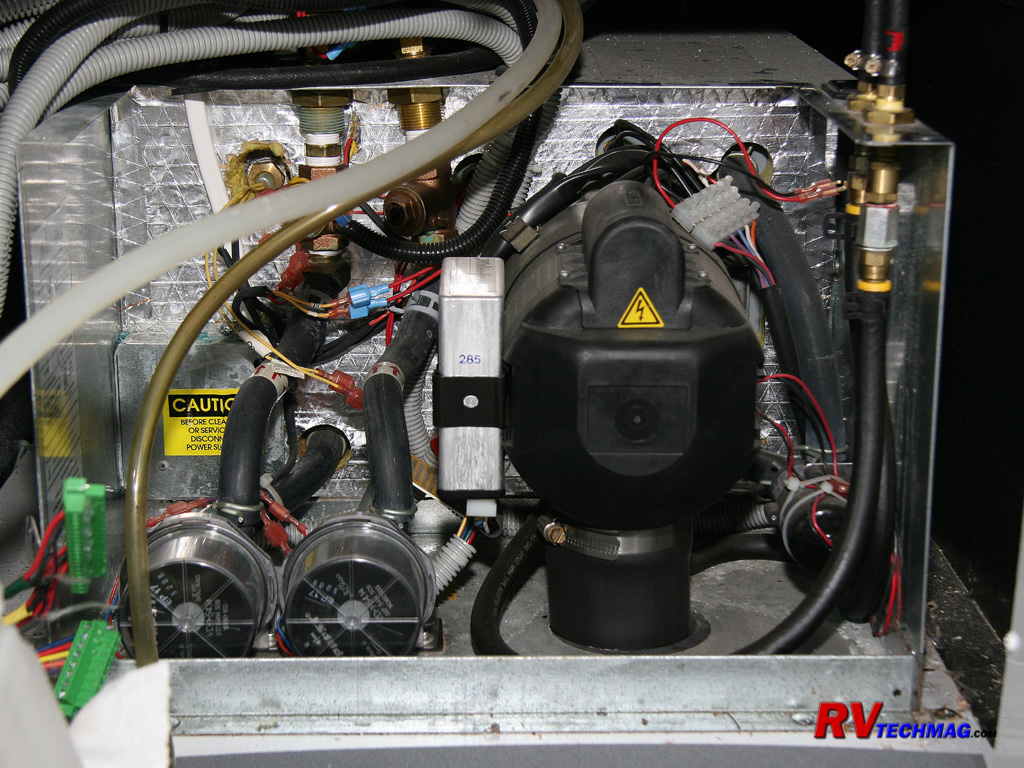
Once the boiler's access panel is removed, it's easy to access the burner assembly. The larger black unit in the center is
the burner and is removed with two eyebolts to service the nozzle and electrodes.
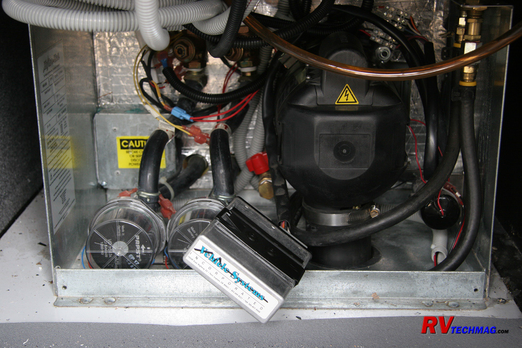
In order to access to two eyebolts that hold the burner assembly in, it's necessary to remove the motor controller box from the
side of the motor. This unit is mounted in a slot and slides off easily. Once it is removed the wiring plugs can be removed to afford easier access
to the nuts on the mounting eyebolts.

Once the motor controller is removed the eyebolts are accessible. There are two eyebolts. One is at the 2 O'clock position
while the other is at the 8 O' clock position. Unfortunately, this lower eyebolt is hidden behind the red valve handle, which is the drain valve for
the boiler tank's antifreeze. Whenever you try to put a socket and extension onto it, the red valve handle gets bumped and you get a mess. So, I
installed a 1/2" brass pipe plug in the end of the open valve. Now I can open the valve fully in order to gain easy access to the eyebolt nut without
having any antifreeze running all over the place. If I ever need to drain the boiler I can simply remove the brass pipe plug.
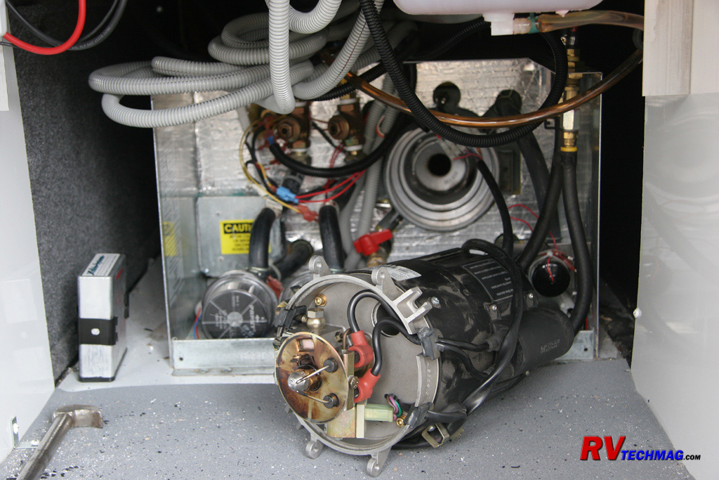
Once the eyebolts are loosened they can be swung out of the way. The burner assembly is easily rotated out of the housing to
expose the burner components. The flexible fuel lines and wiring harness make it a project to remove the entire unit but it's very easy to just swing
it out and service the burner inside the compartment.
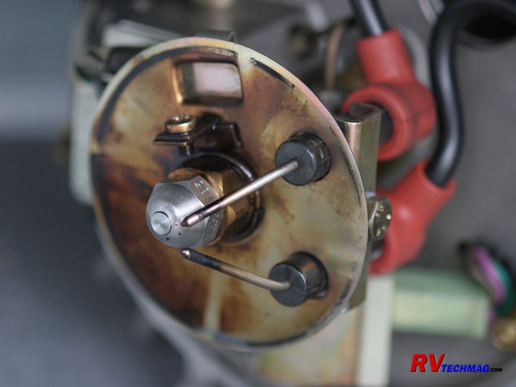
This close-up view shows the serviceable burner parts. At the very top is a photocell that sense whether or not the flame is
lit. This needs to be kept clean from soot. The electrodes also can be cleaned to remove any carbon buildup and they should be checked for proper gap
and spacing. This isn't a frequent adjustment though because once they are set it takes quite a bit of operation before the electrodes would erode
away. Details on proper burner servicing can best be found in the Hydro-Hot Shop Manual on this
website. The nozzle needs to be replaced annually. Be sure to use a 3/4" wrench to prevent the nozzle holder from turning while you place a 5/8" wrench
on the nozzle itself to remove it. Be sure to work clean and not allow dirt to enter the open cavity. Also, NEVER touch the tip of the nozzle in
order to ensure that the orifice remains unobstructed. To Reassemble, simply reverse the process.
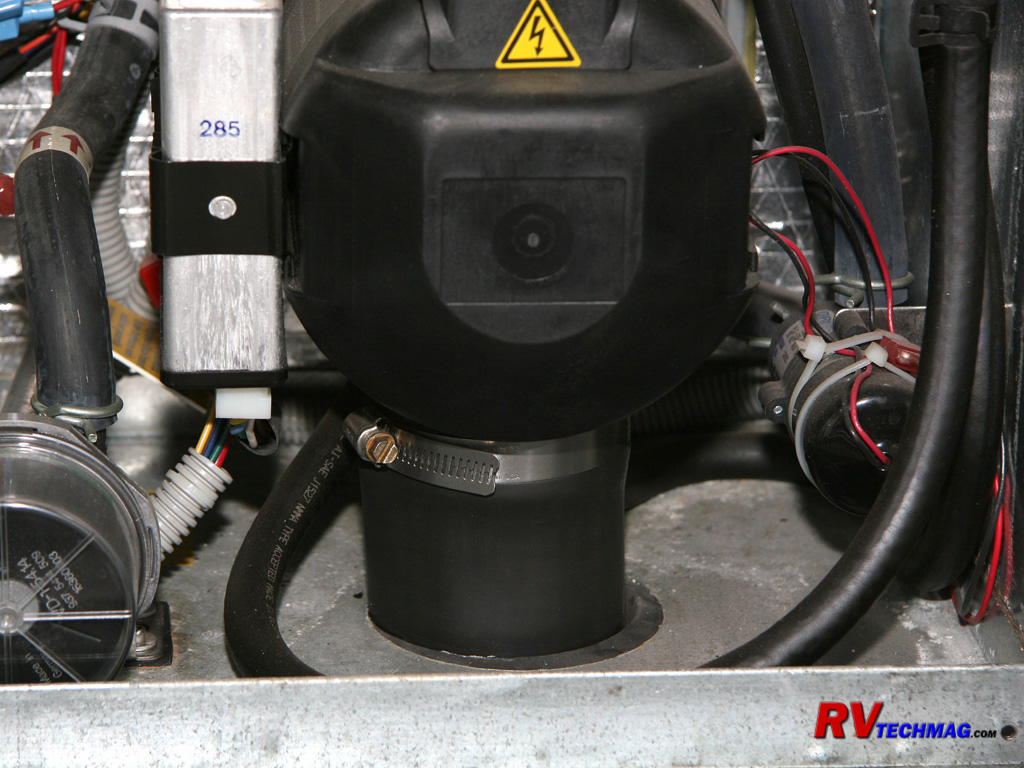
This close-up of the burner shows a rubber hose and hose clamp attached to the bottom. This hose extends through the floor and
serves as an intake hose for the burner's combustion air. This hose has a very thin wall and other owners have found that it tends to collapse when the
diesel burner is running, This restricts the intake air to the burner and makes it run rich and smell. The only reason it's on there is because of some
federal regulation and Hydro-Hot has mentioned that it's not necessary for the burner's operation because it will draw intake air from the outside
anyway because once the access cover is in place it is a sealed area. Many owners have removed this hose. However, I didn't like the fact that the
inside of my Hydro-Hot unit was now exposed to the outside. After having problems with mice chewing on wiring on my home I determined to do something
different on my RV. So, I inserted a piece of mesh into the hose to act as a hose liner so that it couldn't collapse. Two small holes in the hose and a
nylon cable tie holds it firmly in place.
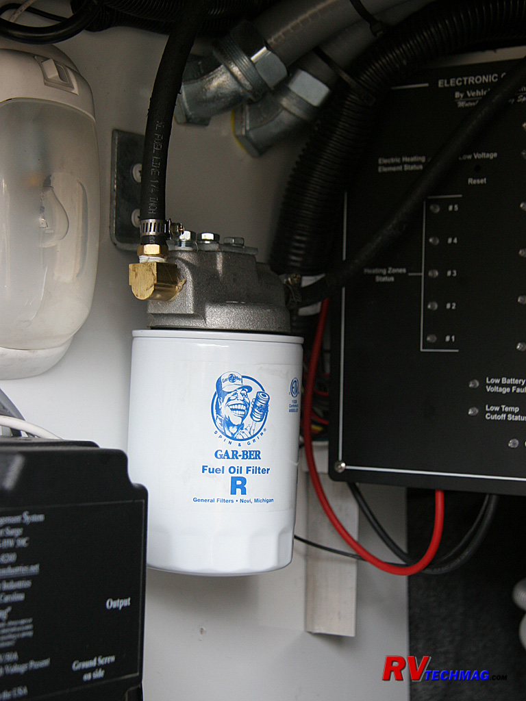
The fuel filter for the Hydro-Hot burner also needs to be changed annually. Originally the hose feeding the filter went in
straight and the tight bend on the hose pinched it off and I had rolling startups and fuel starvation problems. I added a brass 90 degree street ell
to the filter so that the hose could run without any strain or kinking and the fuel starvation problems disappeared. However, whenever it was time
to change the filter, a fair amount of fuel would drain from the lines.
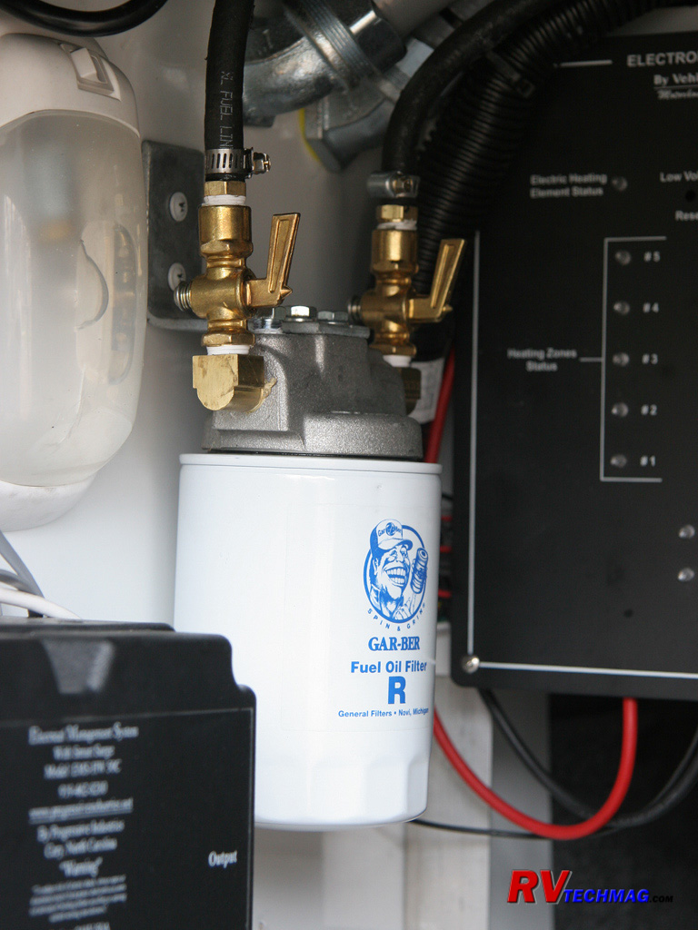
To make it a cleaner task when changing the fuel filter I installed a pair of brass in-line shutoff valves to the filter. Now,
whenever I need to replace the fuel filter, I only lose a small amount of diesel fuel, which is easy to catch in a small pan.
Summary
The end results are many:
- I have a better central vacuum with more power that is now located out of the way.
- I have room for my surge suppressor and Autoformer.
- The cord reel is easily removed and the Autoformer is now plug and play.
- The hour meter is easily seen.
- I have more storage space in that compartment.
- Access to the Hydro-Hot for service is much easier and service time is drastically reduced.
- I now have better fuel flow control over the fuel filter when servicing it.
- The collapsing rubber hose is done away with and the potential for diesel burner smell is reduced.
All in all, it was worth the 6 hours it took to accomplish this task. The benefits and time savings in the long run are well
worth it. I can now remove the cord reel, disassemble the burner, replace the nozzle and fuel filter, clean out the burner tube, and reassemble
everything from start to finish in 30 minutes.
I have one last project left to do. The Hydro-Hot Shop Manual shows rubber padding underneath the boiler assembly in order to
dampen the vibration. Tiffin Motorhomes simply bolts it direct to the compartment floor. I plan on raising the Hydro-Hot unit and inserting some
rubber pads underneath to see if it will allow the unit to run quieter with less harmonic vibration transmitted into the coach.
Return to Home Page
If you enjoyed this article be sure to recommend RVtechMag.com to your friends, like us on Facebook or Twitter
or subscribe to our RSS feed.


|


