Installing a Towed Vehicle's
Auxiliary Braking System
How To Properly Connect a Towed Vehicle's Auxiliary Brake System to Your Motorhome's Air Brake System
Article Date: August, 2016
Article and Photography by Mark Quasius
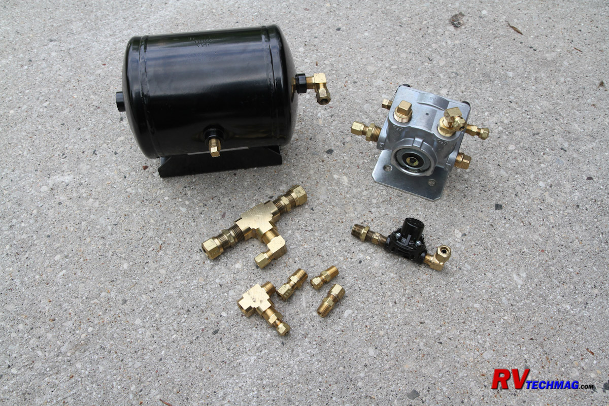
A supplemental braking system is a must for any vehicle towed behind a motorhome. In addition to a reduction in braking
distance, the breakaway feature is an important safety feature to prevent a runaway vehicle should it become disconnected from the coach. Most
diesel powered coaches are equipped with air brakes. Supplemental braking systems that utilize the coach's air supply to operate the brakes on
the towed vehicle are the perfect solution and provide proportional braking between the towed vehicle and the coach. A number of systems are
available, such as the M&G Tow Brake, SMI's Air Force One, Roadmaster's Brake Master and Blue Ox's Brake Safe.
But there is a right way and a wrong way to connect these systems. Any modifications to a coach's air brake system must
be DOT approved and meet federal motor vehicle safety standard FMVSS 121, which requires protection of the coach's air brake system in the event
of a failure of the supplemental braking system.
Disclaimer:
Tapping into your coach's air brake system is not to be taken lightly. This article explains the process used to install a safe DOT approved system
to allow your coach's air brakes to safely operate your towed vehicle's supplementary braking system. An additional intent of this article is to
illustrate hopw the system operates and why it is important. If you are not comfortable with working with air brake systems you should have this
kit installed by a professional installer who is experienced in air brake systems.
Reasons for Protection
In order to have a proportional braking system on your towed vehicle you cannot just supply the supplemental braking system
with air pressure. You will need to access the coach's braking system to provide a variable air supply to the towed vehicle so that the operation
of the supplemental system is proportional to the coach's braking system. If you simply tap into one of the lines supplying a brake chamber you risk
the potential of losing braking ability on that axle should the supplemental system fail or the umbilical hose connecting the two vehicles sever or
disconnect. FMVSS 121 requires protection to isolate the supplemental system from the coach's primary system.
The correct way to do this is to install a small reservoir tank, pressure protection valve and quick release relay valve.
The reservoir tank will be charged with air from the coach's primary air tank, which supplies the rear axle brakes. The pressure protection valve
ensures that the reservoir tank will be supplied with air from the main line connected to the primary air tank but will stop all air flow once the
pressure drops below 90 PSI to prevent the primary air system from draining down and locking up the spring brakes should a failure occur in the line
coming from the reservoir tank. A pneumatic relay valve is then installed that takes air from this reservoir tank and outputs it to the towed
vehicle air connection. The trigger port on this quick release relay is then connected to the drive axle relay valve via a tee fitting. The relay
is then proportionally actuated in response to the brake pressure supplied to the rear axle brakes. This method will not draw any air from a brake
chamber and will not affect the coach braking should any failure occur in the supplemental braking system. The air used to operate the brakes on
the towed vehicle is handled by the small reservoir tank.
My System
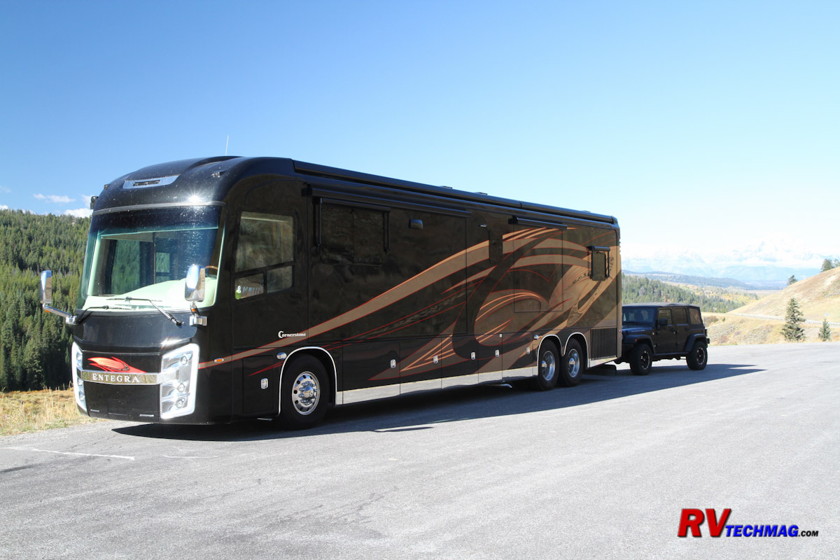
In my case I have a Spartan K3 chassis and a Jeep Wrangler with an M&G tow brake system. I've used the M&G system on the
last two coaches and three Jeeps and was very happy with the system. But on our previous coaches I just inserted a tee and tapped into one of the
tag axle brake lines. While this method did work, it did result in a slight reduction in braking efficiency at one of the tag axle wheels because
the air was being split off to the Jeep as well as to that particular wheel on the coach's tag axle. In addition, should the brake hose that
connected the Jeep to the coach ever disconnect or break I would most likely only have brakes on five out of the six wheels on the coach. So for
this coach I decided to do it right. Fortunately Spartan makes a kit that includes everything I needed to complete this project and cost right
around $300. This is Spartan's S-1628-0012 Towed Vehicle Braking System Kit, which includes everything you'll need plus enough extra fittings and
nylon air brake line to cover any specific coach configuration.
The Installation
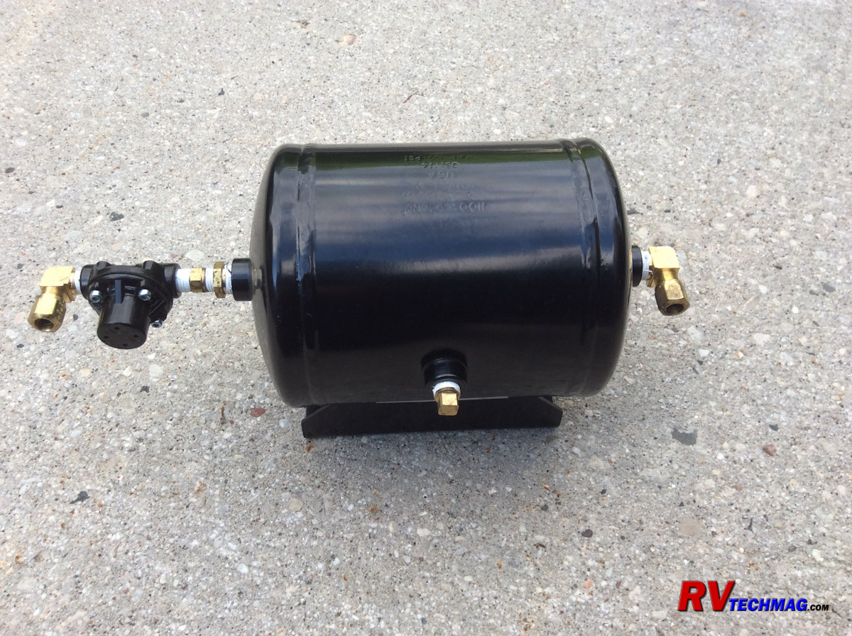
The first step was planning where to place all of the components. Ideally they should be in reasonable proximity to the
drive axle brake relay valve to minimize having to run the brake lines over long distances. I found a spot beneath a crossmember close the drive
axle valve that had two pre-drilled holes that aligned perfectly with the holes in the relay valve's mounting bracket. I also found a good spot
for mounting the air tank reservoir that was a safe and secure location that didn't interfere with any other components.
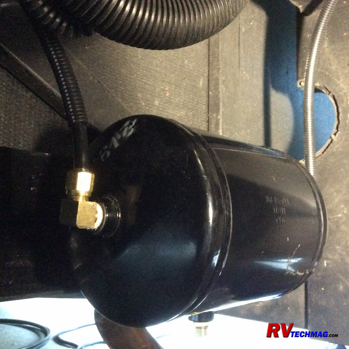
I began by mounting the tank. I made an adaptor plate so that I could bolt the tank to a nearby angle iron cross-bar,
drilled the appropriate holes in the plate and bar and used bolts with nylon locknuts to permanently secure the tank.
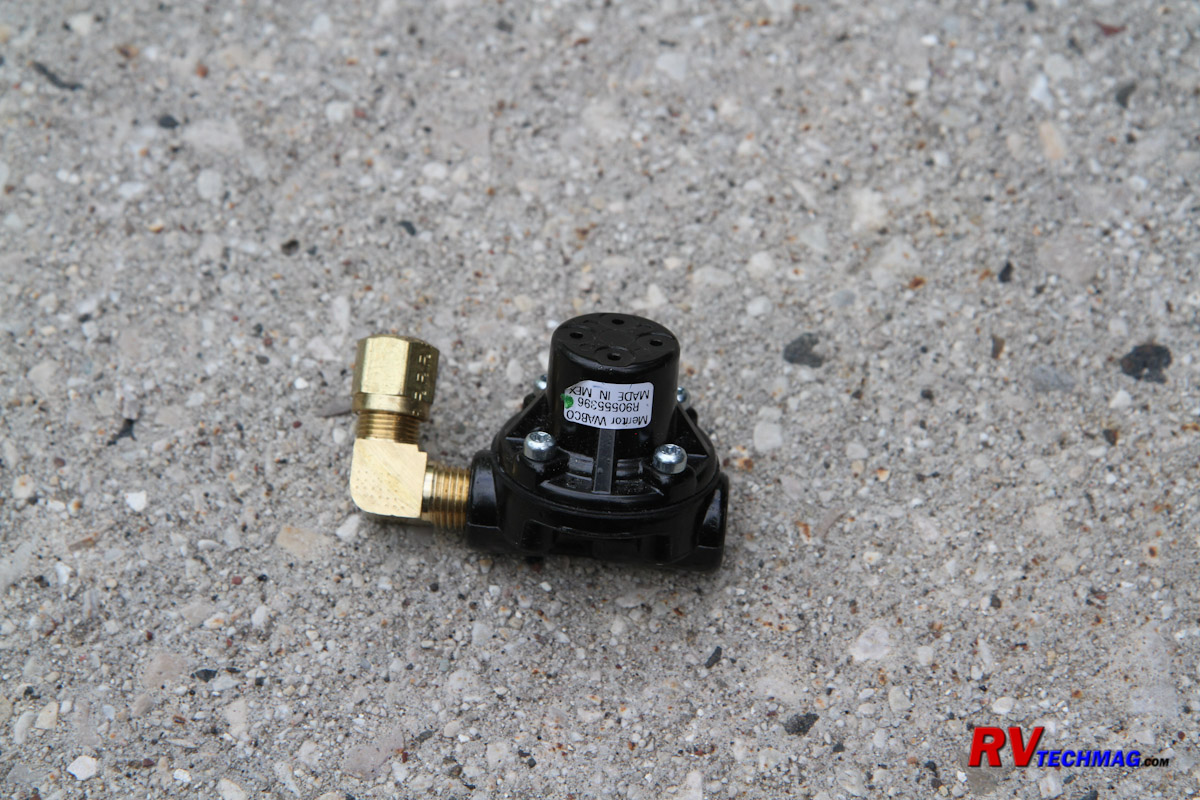
The tank had female threaded connections on each side of the tank so I decided which end was best suited for running
the air line to the supply side and installed the pressure protection valve into that end, being careful to ensure that the arrow on the valve
faced the tank.
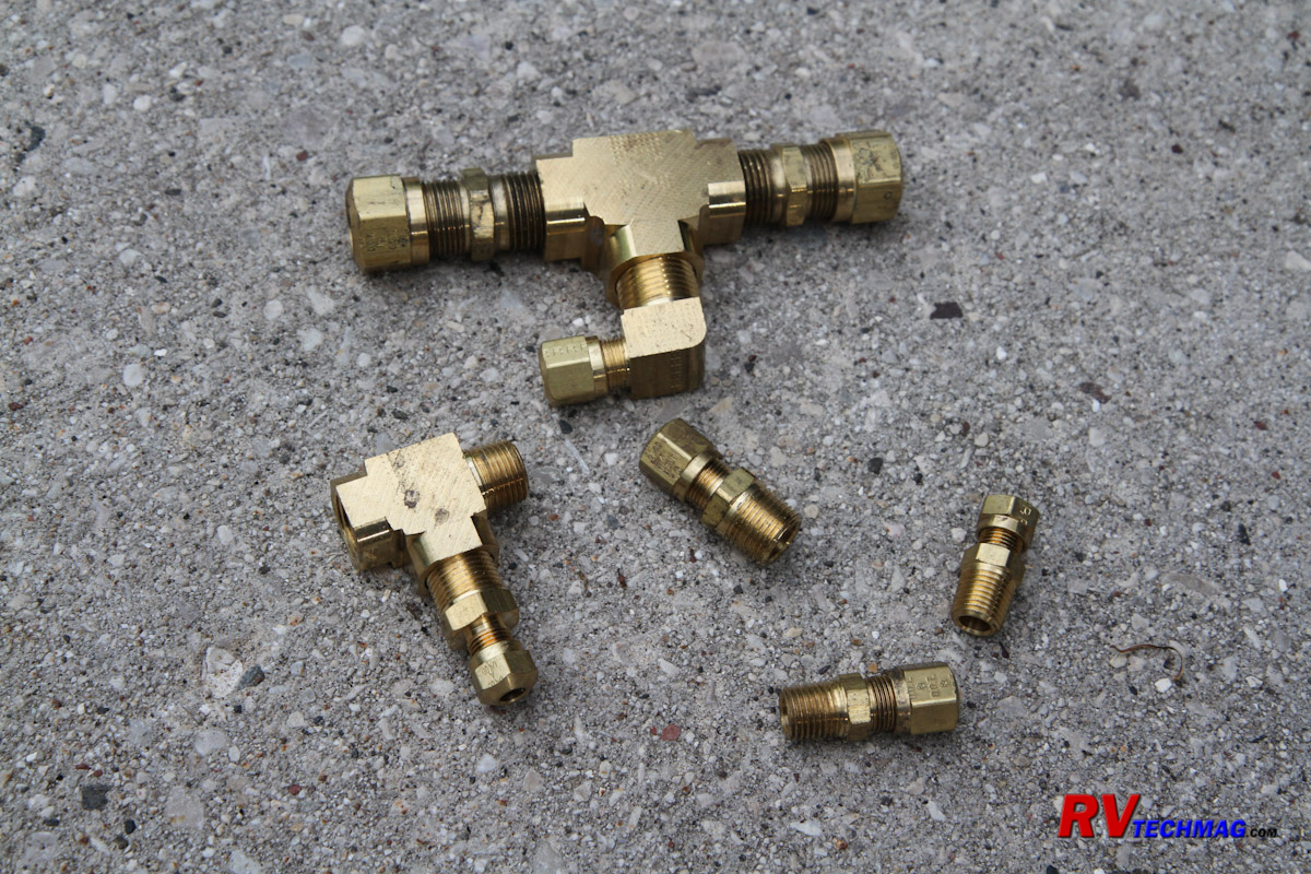
The kit includes plenty of extra fittings so that you can use straight connectors or right angle connectors. In this case
I chose the right angle connectors to eliminate any excess bends in the air lines.
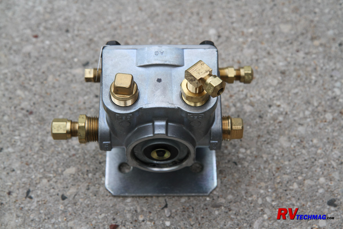
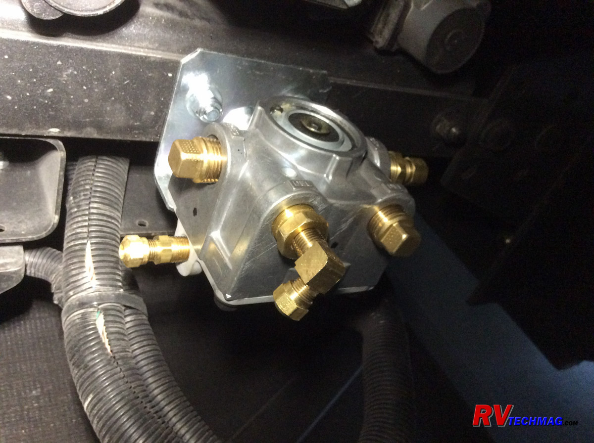
I then mounted the quick release relay valve. The holes were pre-drilled in the crossmember but another bracket was
present in the crossmember's channel that blocked those holes so I needed to drill that bracket with matching holes so that I could insert the
mounting bolts for the relay valve. I used a blind hole centering punch and drilled that bracket, then inserted a pair of bolts with nylon lock
nuts and mounted the relay valve. The relay valve has labeled ports for supply, delivery and control. There are two ports for every hose connection
so you only need to use three of the six ports. The other three are sealed off by the threaded pipe plugs supplied in the kit. Again, I chose the
ports that offered the best place to connect the lines to and inserted plugs into the other connections.
Now that the main components were installed it was time to run some air lines. The drive axle brake relay valve is supplied
with a large diameter air line that runs from the primary air tank in the front of the coach to the drive and tag axle braking systems. I needed
to tap into this line with a tee fitting that was included in the kit so the first step was to drain the air tanks. Technically you would only have
to drain the primary tank but I chose to drain all three tanks just to be sure I was safe. Brake systems do have a standard color code for air lines
as well as air tank drain valve lanyards. Green is for the primary system that supplies the rear brakes while red is for the secondary system that
supplies the front brakes. I found the large green air line that ran to the drive axle brake relay valve, measured it and found it to be a 5/8" line.
The kit came with fittings for both 5/8" and 3/4" lines so I assembled the tee fitting with the 5/8" connectors and sealed the threads up with Teflon
tape. I then used a Pex cutter to cut the existing 5/8" line and remove a small section of tubing, equal to the length of the tee fitting that was
to be installed, making nice, square cuts with my Pex cutter. The tee was then put into place and the fittings tightened with wrenches. A 3/8" nylon
air brake line was then run from the branch of the tee fitting to the pressure protection valve on the reservoir air tank.
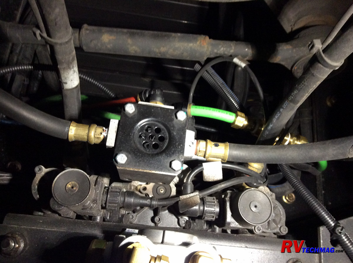
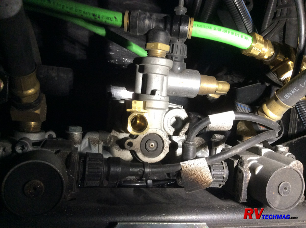
In order to send a signal to the relay, a connection to the existing drive axle relay valve needs to be made. This requires
removal of the brake valve that sends air to the drive axle brake chambers, inserting a street tee into the relay valve, then reinstalling the
brake valve. A small 1/4" diameter brake line is then run from that tee to the control port on the new relay valve that operates the supplemental
braking system. I actually found it was easier to run that line prior to reinstalling the large brake valve on the drive axle that would obscure
the small tee fitting between it and the drive axle relay valve.
The next step was to run another 3/8" line from the air tank's output port to the supply port on the relay valve. At this
point I decided to test the system for leaks and operation. I started the coach engine and built up air pressure. Once the air governor kicked out
I shut off the engine and went back to check for leaks. Everything was quiet so I had Leann step on the brake pedal gradually to see if I had
proportional air flow on the relay valve's delivery port, which was not yet connected. The air exited the valve just as it should so it was now
time to run the final line. I ran a 1/4" brake line from the relays valve's delivery port to a female quick disconnect coupler that was mounted back
by the trailer hitch lighting socket. This line, as well as any other lines used during the install were wrapped in plastic split wiring loom to
help protect it from abrasion. All lines were also fastened in place with nylon cable ties.
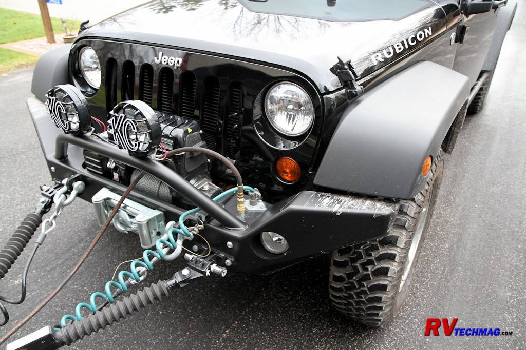
The end result is I now have a supplemental braking system that is totally proportional with the coach brakes and is
isolated from the coach brake system. This protects the coach brake system from loss of braking capacity should a failure occur in the supplemental
braking system. This system meets the federal FMVSS 121 regulations and is approved by both Spartan and Freightliner and will not affect any
chassis warranty nor cause an liability issues due to an unapproved modification to the braking system in the event of an accident. In addition to
the kit all I needed to complete the project was a bit of plastic wire loom, some Teflon thread tape and a few nylon cable ties.
Sources
Spartan Chassis
(800) 722-3025
www.spartanmotors.com
Spartan Chassis
(800) 722-3025
Link to Spartan Installation Instructions (TSB04-250-001)
Return to Home Page
If you enjoyed this article be sure to recommend RVtechMag.com to your friends, like us on Facebook or Twitter
or subscribe to our RSS feed.


|


