MCD Innovations: Made in the Shade
Upgrading an RV's Pleated Day-Night Shades and Visors
Article Date: May, 2009
Article and Photography by Mark Quasius
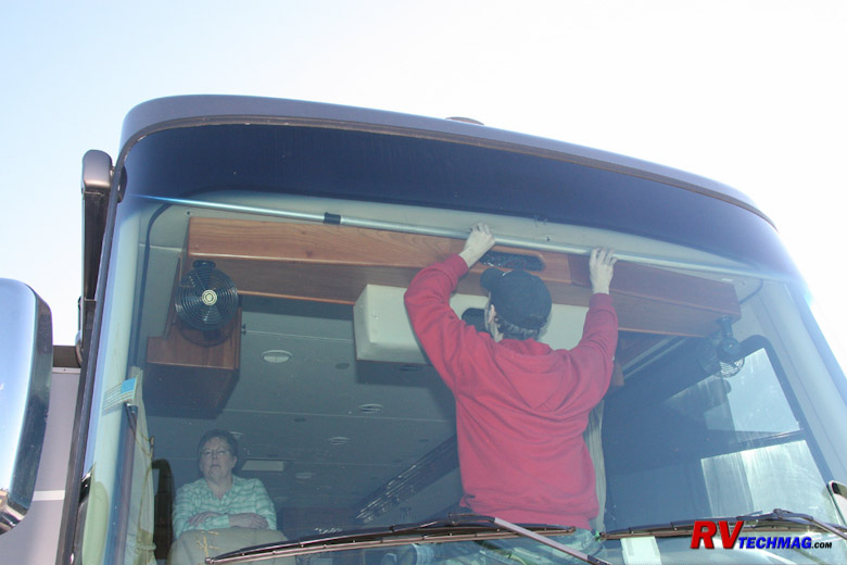
Remote Powered Shades Installation
In previous chapters we covered the installation of MCD's dual range powered windshield shades on our 2007 Allegro Bus as well
as some manually operated shades in the living area. We also installed some remote powered shades in the cockpit side windows and in the main living area.
This topic will cover MCD's remote powered shades - how they work and how they were installed. For all practical purposes we will not be referring to
MCD's dual range powered windshield shades because they use a different control method as well as the dual range safety feature that operates when the
ignition is on. For information on windshield shade installations please refer to the Windshield Shades Installation tutorial.
MCD's powered remote controlled shades are a unique, compact design. A 12 volt motor is inserted into the shade roller and does not
take up any additional room in the valance. Powered shades can be located anywhere that a GlideRise IV manually operated shade can be located. The powered
shades can be used in MCD's American Solo single roller systems or can be part of the American Duo dual roller systems. Dual roller configurations allow
for dual manual shades, dual powered shades, or a hybrid design using one manual and one powered shade.
The motors are powered by 12 volt battery power. Each motor is fed a pair of wires, a hot feed and a ground. The feeds are
constantly hot, not switched, so you can tie into any available nearby 12 volt source. Each motor draws 800 milliamps under load (.8 amps) so the
current draw is very small. Each motor contains a radio receiver and some electronic memory to hold the various parameters and settings. Wireless
remote controllers communicate with each motor to operate them as well as to program the various settings. It's a fairly simple task to modify any
shade's parameters or relocate to a different switch. Unlike the GlideRise IV manually operated shades, the remote powered shades use digital memory
to set the auto-stop positions so there are no adjustment knobs on the shade itself. Everything is done from the remote controller.
In the following paragraphs I'll detail the actual process used to install MCD's remote powered shades in our 2007 Allegro Bus
and explain in more detail how the various controllers function.
Product Overview
|
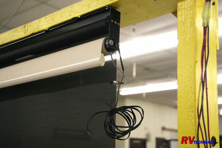
Powered Shade Assembly.
|
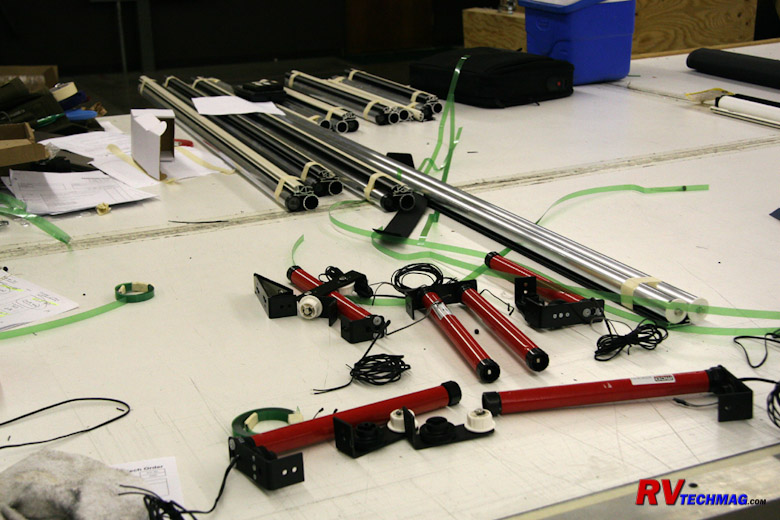
Powered Shade Components.
|
In the upper photo a remote powered shade is hung from a test stand at MCD. Every unit is tested prior to shipment. This image
shows two sets of wires. One pair is the 12 volt hot and ground that powers the shade. The other pair connects to a small pushbutton which is used to
short those two wires out in order to initiate the programming mode on remote controlled shades or to set the stop limits on a dual range powered
windshield shade. Once the shade is programmed the button is no longer needed. It can be left in place and tucked above the mounting track or it can
be removed if desired. The lower photo shows the various components that were used to assemble my shades. Some of the roller tubes are visible on the
assembly table as are the various brackets. The motors are the red tubular items that also contain the electronic components required to communicate
with the remote controllers. As you can see, they are a nice compact package and provide a quality, trouble free product.
Measuring and Planning
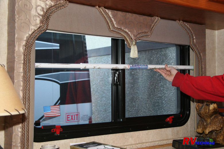
Measuring the Valance
The best way to obtain an accurate measurement of the inside width of the valance is to use an extendable pole. Extend the
pole until it touches the inside of the valance. Then move it up and down inside the valance to check for any tapering. If the valance is slightly
tapered be sure to take the smallest measurement to prevent binding. If you don't have a pole then you could jury rig two yardsticks and clamp them
together with vise grip pliers. Either way, it'll be easier and more accurate to measure your pole or whatever later. Next measure the height of the
valance with a tape measure. Be sure to measure according to the detailed instructions found at This Link. MCD will automatically add additional
shade material to your measurements to facilitate wrapping around the shade roller. They will also allow for clearance within the valance so just
measure the valance and let MCD deal with the actual shade size.
|
Removing the Valances
|
Bare Window Frame.
|
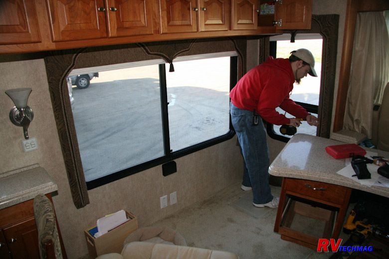
The pleated shades snap into some retaining brackets mounted into the top of the valance. But they tend to pop free and the
shade can fall so Tiffin added an extra screw to help pin the shade into the valance brackets. However, they install this screw on an angle and then
mount the entire valance and shade as an assembly which means that you cannot get to this screw when the valance is mounted to the wall. Therefore,
it's easiest to remove the entire valance to gain access to the shade.
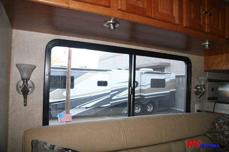
Once the valances have been removed the bare window frame will be exposed. The pleated shades can now be easily removed from
the valance. In addition to height and width you also need to check the depth of the valance. The shade and roller needs a minimum of 2" depth in
order to fit and operate properly. Some valances were not that deep because they were designed for the slightly narrower pleated shades.
Modifying the Valances
Attaching Drapery Cording to the Valances
Our 2007 Allegro Bus was one of the coaches that had the narrower valances. I did barely have the 2" of depth to the wall
but the window frames stick inboard a bit. While the shade rollers did fit, the window frames interfered with the hem rails and tended to stick and
bind. In recent years the valances were made deeper to accommodate MCD roller shades but my coach was one year too early to benefit from that. Rather
than go through the expense and time of making new valances it was much easier just to space me existing valances out from the wall a bit. I didn't
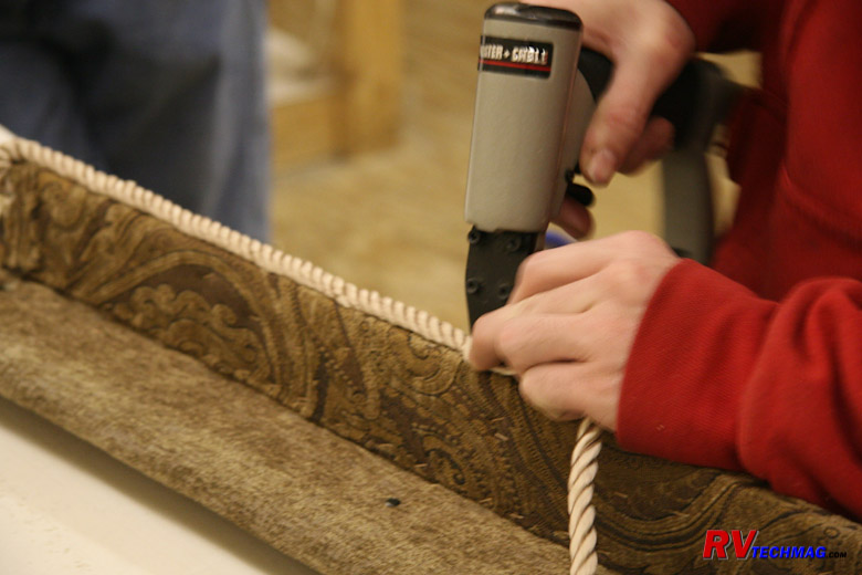
need much more room but it still needed to look attractive as well. What is generally done in those cases is utilize drapery cording, commonly used
to create tie backs for drapes. This stuff is popular, comes in many colors, has a nice satin sheen, and is 1/2" in diameter, which is perfect for
what we need. We used a color that went well with my existing valances and stapled the cording to the backside of the valances - effectively spacing
them out from the wall enough to ensure smooth operation of the shades. The end result was that it looked like it came from the factory that way and
was part of the valance.
Wiring the Shades in the Living Area
Connecting to the Dinette
Without a doubt, the most time consuming task with installing powered shades is getting power to them. Initially I thought this
was going to be a huge undertaking and had visions of my ceiling all torn out with wiring hanging down all over. Fortunately, it wasn't that bad. When
you stop to think about it, there's 12 volt power all over the coach. Because the shade motors draw such little power it's not necessary to provide a
dedicated fused circuit for them. All you have to do is tap into a nearby circuit. The shades do require power to operate so you'll need to find a hot
source, rather than tap into a light or other device that is controlled by a switch. Otherwise your shades won't work unless you turn the light on.
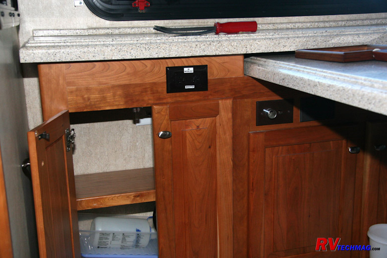
12 Volt Outlet in the Dinette
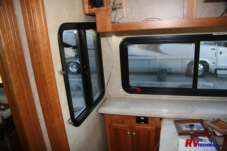
On the dinette side of the coach it was easy. Most dinettes come with a 12 volt power socket to run a laptop computer or other
12 volt devices. All you have to do is run that power up to the overhead cabinets and then over to the shades on that wall. After the valances were
removed a wire was run from the 12 volt receptacle in the dinette counter and up the corner of the slideout wall. Once the valance was reinstalled that
wire was tucked behind it and hidden so that it was no longer visible.
|

Removing the Cabinet Doors
|
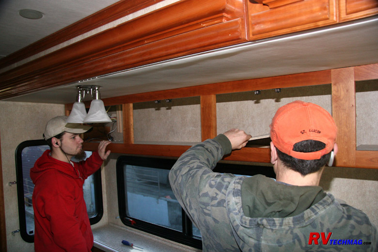
Removing the Cabinet Floor.
|
The four shade valances on this wall butted up underneath the overhead cabinet that ran the full length of the slideout.
Therefore we could hide the wires in the overhead cabinet so that they would not be seen. The cabinet is of sturdy hardwood construction and a 1/4"
plywood floor is placed inside the cabinet and covered with a non-slip material that's a cross between felt and very thin carpeting. This floor is
then stapled down to the crossmembers in the base of the cabinet. This was the perfect spot to run our shade wiring. Using a series of pry bars we
carefully pried up the floor of the cabinet. However, the adjustable hinges for the cabinet doors intruded into the cabinet so we could not lift the
flooring up high enough to gain access. The solution was to remove the cabinet doors, making sure to number them so that we wouldn't have to realign
all the hinges when reinstalling them. The cabinet flooring then lifted right up and we tucked it into the top portion of the cabinet to keep it out
of the way.
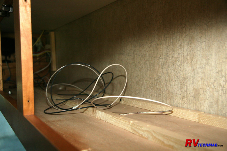
Running the Wires in the Cabinet
The wires were then run to the far end of the cabinet and splices were made to provide four drops, one to each of the shades.
If you are installing both daytime and nighttime shades you'll need to double the number of wiring drops. It would be best to make those splices inside
the cabinet rather than in the valance because there is less room in the valance to do this. The wires will need to exit the cabinets near to where the
shade motors will be. The motors themselves are bidirectional so they can be located on either end of the shade roller. The choice is made upon which
end is easiest to connect to and is made prior to building the shades. Once the wires have been run through the bottom of the cabinets a fair amount of
slack should be allowed. Eventually spade type quick disconnects will be crimped to their ends to facilitate ease of installation and removal. But it's
much neater to drill very small holes into the top of the valances and cabinet bottoms to pass the wires through rather than large holes to pass the
wiring terminals through. The wire terminal connectors can be added to the wires after the valances have been reinstalled so just leave those wires
hang for now. The excess wire can easily be pushed back into the cabinet cavity later on.
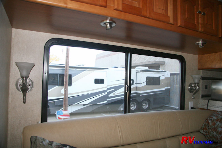
Passenger Side Turret Lamps
The passenger's side was a bit easier. We did need to remove the doors and pry the cabinet flooring up, just as we did on the
driver's side slideout. However, the overhead cabinet in the passenger side slideout had turret style reading lamps that were controlled by integral
switches, which meant that 12 volt hot power was fed to those lights. All we had to do was tie into those wires to supply power to the shade over
the couch.
The small shade over the kitchen windows was done in similar fashion. After removing the cabinet flooring we were able to
connect to the wiring that fed the fluorescent under-cabinet light fixture in that cabinet.
Wiring the Side Shades in the Cockpit Area
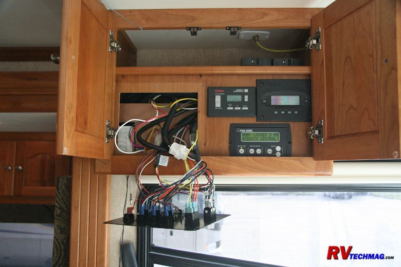
Powering the Driver's Side Shade
The driver's side shade also required 12 volt power. Normally the procedure is to remove the left side A pillar trim and run
a wire up from the dash area, through the A pillar trim, and back through the overhead cabinet to the driver's side shade. You can connect to any 12
volt constantly hot power source found within the dash. Because the shades only draw 0.8 amps it's not necessary to provide a separate fused circuit
for them. In my case, I already had 12 volt power in the cabinet directly above the driver's seat. A 12 volt battery feed was supplied to my Onan
EC30 Automatic Generator Start module so I simply tapped into that wire. Depending on how your coach is outfitted, you may or may not be able to
locate a 12 volt source in that cabinet. If you cannot find one, you'll have to go through the A pillar trim to access the dash area.
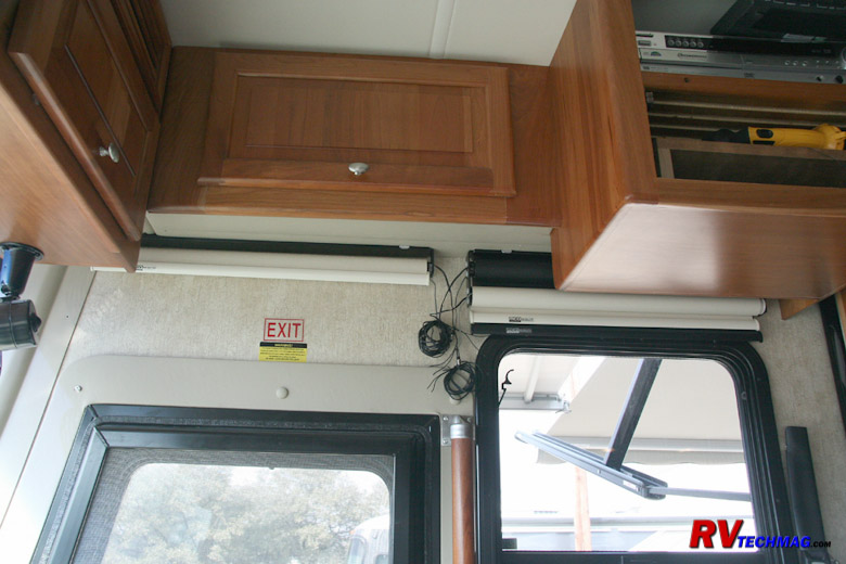
Accessing the Antenna Booster Cabinet
Power was provided to the shades that cover the entry door and copilot's side window power once again by dropping wires down
through the overhead cabinet. Many coaches use a Winegard video selector switch that selects between cable TV, satellite receiver, antenna, DVD, etc.
The units generally have a button to push that lights up a red pilot lamp and powers an antenna booster for use with the standard batwing TV antenna.
This amplifier requires 12 volt power so this is an easy to access power source. If you do not have this kind of video selector you may be able to
find 12 volts at a map light or any other light as long as the power is constantly hot, and not switched. If you do not have any power in that cabinet
you may be able to find something in the front cap, behind the TV. Chances are that if you don't have the coaxial cable selector switch you will have
an antenna booster switch someplace in the front overhead cabinets. If none of these conditions exist you may have to run your wires down through the
passenger side A pillar trim and tap into a source behind the dash. In my case I did have the antenna booster so it was an easy task to tap into those
wires and supply those shades.
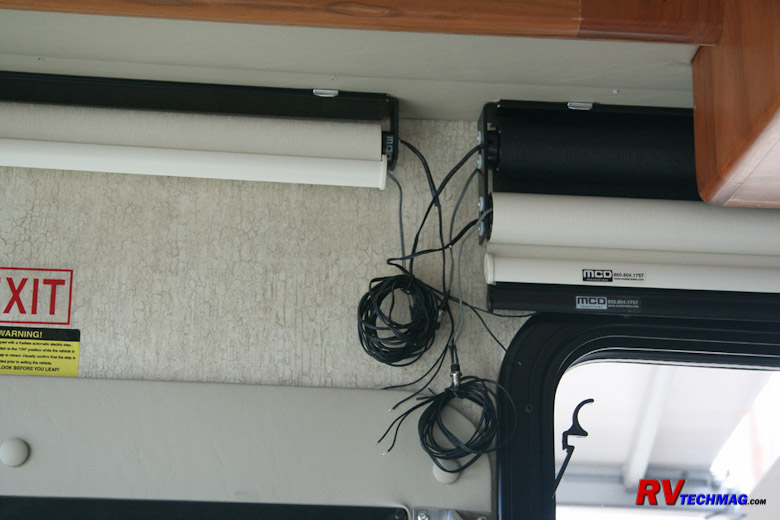
Powering the Copilot's Shades
When planning your installation it's important to plan both the direction the shade will roll off the shade roller as well as
where the wiring will be connected. Normally you want the shade material to roll off the backside of the shade roller so that the shade is closest to
the wall in order to minimize light penetration by keeping the gap between the shade and window frame as tight as possible. Sometimes it's not feasible
to do this because the window frame is too fat. This was the case with our entry door. The screen door jutted into the coach so that particular shade
was configured to roll off the front side of the shade in order to give it more clearance. However, the shade still laid flat against the screen frame
when extended. Once this rotation direction has been decided, it's easy to plan on which end to locate the shade motor. As you can see in the above
photo, the shades are arranged so that all of the wires are bunched in one common location. This makes it much easier to run wiring to the shades and
provides a nice clean look to the installation. By drilling one hole up into the base of the overhead cabinet it was easy to fish the wires forward to
the antenna booster's 12 volt power source.
Mounting the Shades
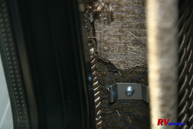
Track Mounting Clip
Sometimes it's easier to mount the valances first and then snap the shades into place and sometimes it's easier to clip the
shade into the valance and then mount the entire assembly. If that is the method you choose it would be easiest to hold the baser valance up in place
to mark where the wires will need to pass through the valance. Once you have carefully marked exactly where the wires will enter the top of the
valance drill a small hole to allow the wires to pass through the valance. If you choose to install the shades after the valance is up be sure to
first install the mounting clips that will hold the shade to the valance.
MCD shades come mounted via either a single roller or dual roller bracket to a mounting track. This track snaps into place on
the ceiling into a number of mounting clips. The number of clips depends on the width of the shade. If the shade is 29" or smaller two clips will be
fine. For shades that are between 30" and 60" in width three clips will be required. If your shade is larger than 60" in width four clips will be
required. Place one clip near each end and evenly space any remaining clips over the width of the shade. Be sure to properly locate the shade in the
valance. Properly center the shade from left to right within the valance but do not center it depth-wise or else the shade may catch on the window
frame, which intrudes into the valance. In order to allow for the width of the window frame, plus the screw heads you'll probably need to allow 1/2"
of clearance on the back side. After allowing for this clearance you can then center the shade brackets within the remaining area. If you place the
shade too close to the outer edge of the valance it will rub on the inside of the valance and bind. Conversely, if it's too close to the window frame
it'll catch on the screw heads and bind. The mounting clips do have slotted mounting holes so be sure to locate your screw in the very center of the
slot so that you can adjust the shade in either direction if necessary. Also, before mounting the valance check the condition of the screw heads on
the window frames. If the screws have any sharp burrs on them from when they were installed it would be a good idea to file them off so that they can't
cut the shade when it glides past them. Once the brackets are installed into the valance you can either mount the valance to the wall, then simply
snap your GlideRise IV shade into the brackets or snap your shade into the valance and then mount the entire assembly to the wall, depending on which
way is easiest.
When you are ready to install the valance hold the valance up to the wall and slide your wiring tails through the hole in the
valance. Then fasten the valance to the wall and overhead cabinets. Once the valance is fastened down crimp a pair of wire terminal spade disconnects
to the ends of the wires. Allow enough slack to make it easy to access. Don't cut them too short because you can always shove the excess back inside
the cabinet cavity. Crimp another set of spade disconnects to the wires on the shade itself. Try to put a male and female disconnect on each shade and
on each wiring drop. MCD shades are polarity sensitive so it is important that the 12 volt positive wire is connected to the black wire with the white
stripe on the MCD shade motor. By installing a male connector on one motor wire and a female on the other you'll be assured that the wiring will not
get crossed if you ever remove and reinstall the shade for whatever reason. Once the wiring has been completed, simply snap your MCD remote powered
shade into the mounting brackets in the valance.
New Valance Trim for Cockpit Side Shades
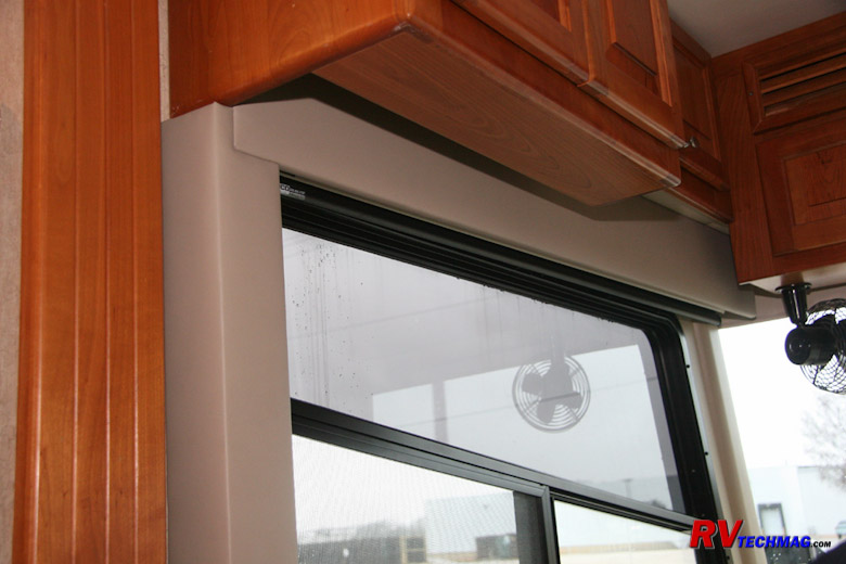
In the main living area we had existing fabric covered valances that just needed to be spaced out a bit. However, the cockpit
side shades did not have any valances. There were no privacy shades because they relied on drapery to provide privacy at night. The only sunscreen
shades were the bug screen shades on rollers that just hung in plain view from the overhead side cabinets. Now that we were upgrading to MCD's American
Duo dual roller shades it was desired to trim that area up a bit to conceal them from view. To accomplish this MCD fabricated some new panels to create
valances that would do a nice job of concealing the shade rollers. They did an excellent job on these and upholstered these plywood panels with foam
padding and a vinyl covering that was an excellent match for the coach interior. It actually looks better (and more original) than the wood boards that
Tiffin uses in the latest coaches. The valances eliminate any gaps around the edges of the shades, there is no light penetration at night, and there is
total privacy because it is impossible to see in from outside the coach.
Programming the Shades
Remote Control Keypads
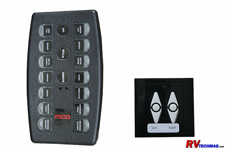
MCD Remote Powered Shades are controlled wirelessly by remote controls. Each shade can be programmed to respond to any number of
controllers and each controller button can be programmed to control multiple shades if desired. This allows a very flexible method to control your MCD
powered shades. Controllers come in two sizes - a 14-channel and a two channel controller, as illustrated in the above photos. Two channel controllers
are typically used to control a single shade location, such as a cockpit side shade, while 14-channel controllers handle a large number of shade
positions and typically are used for the main living area. These controllers are wireless and use batteries to operate. Because the controllers require
no external wiring connections they can be used as portable hand-held remotes if desired, surface mounted to a wall surface with hidden screw locations,
or recessed and mounted within the wall, as is popular with the 14-channel remote controller. In our particular situation we chose to mount the two
channel controllers for the side cockpit windows but to leave the large 14-channel remote loose so that we wouldn't have to run back to a wall location
to operate the shades. We can always mount it later if we change our minds.
Programming the Shades
Programming Button
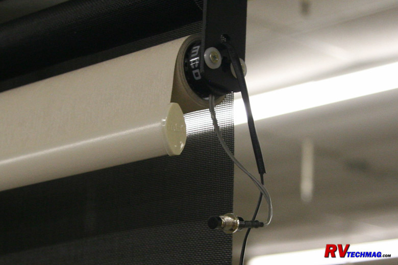
Each powered shade is provided with two short wires that attach to a small pushbutton. This button is pressed to enter the shade
into its programming mode on remote controlled shades or to set the stop limits on dual range powered windshield shades. The buttons do not need to be
present during normal operation but it won't hurt to leave them in place either. If you find that there's not much space in the valance you can unplug
them and keep them in a desk drawer and retrieve them if you ever need to reprogram the shade. While it's true that shades can be assigned to any number
of controller buttons, each shade does need to be married to a specific controller. This defines that controller as the master controller for that
particular shade. The master controller will be used to set upper and lower auto-stop positions and to define the proper motor rotation direction for
the correct up and down motion of the shade. Once this is set, the shade can easily be added to any other controllers or buttons. The best practice is
to use the two channel remote controllers as master controllers for the cockpit side shades, then assign the 14-channel remote as the master controller
for all of the shades in the living area. Note that the dual range windshield shades are not wireless and those limits will be set by the rocker switches
that control those shades. For exact programming instructions please refer to the MCD Owner's Manual.
14 Channel Remote
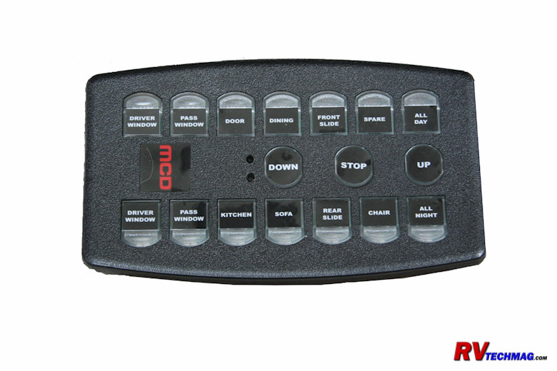
The 14-channel remote can be configured in many ways. MCD will label the various buttons to match the configuration of your
particular coach. If you are installing both powered daytime and nighttime shades each row will generally feature the same labels with the daytime shades
on the left row and the nighttime shades on the right row. In my case we were using MCD's GlideRise IV manually operated shades for the daytime sunscreens
and only powering the nighttime privacy shades in the living area. So, we had plenty of extra buttons available. We included both the daytime and nighttime
powered shades from the cockpit side windows on the available unused buttons. At the top of each row we added "All Day" and "All Night" buttons. Pressing
the "All Night" button operates every remote powered nighttime shade in the coach, including the cockpit side shades. The windshield shade is controlled
by the rocker switches in the cockpit and will not be controlled by the remote controllers. Pressing the "All Day" button operates both of the cockpit side
window day shades. Overkill? Maybe, but the buttons were there so why not use them. Actually this gives three way control over the cockpit side shades.
They can be operated by the two channel remotes at each window, by one of the specific shade buttons on the 14-channel remote, or by the "All Night" or
"All Day" buttons on the 14-channel remote. This system is very flexible and you are unlimited as to how many remotes you want to use and where you
would like to locate them.
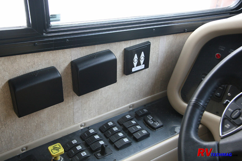
2 Channel Remote by Driver's Side
This hybrid system has really been a great way to go. The daytime sunscreen shades with GlideRise IV technology are easy to
operate. When sitting at the desk or on the couch, you simply reach up and pull the shade down if it gets too sunny. If the sun goes away you can just
give it a tug to have it retract, although with MCD's ClearView technology it's so easy to see out of the coach that you probably won't be retracting
them al that often. The power privacy shades in the living area are generally only operated in the evening to lower for privacy, or in the morning to
raise them back up. The powered cockpit side shades are a real treat. The daytime sunscreen really knocks out the sun's heat and glare when driving
and the privacy shade can also be partially lowered as a sun visor on either the side windows or the windshield. Plus it's quite impressive to others
when you press one button and all the shades operate at the same time. The MCD system really is top of the line.
In the next section we'll discuss how to adjust your MCD manually operated shades.
Return to Home Page
If you enjoyed this article be sure to recommend RVtechMag.com to your friends, like us on Facebook or Twitter
or subscribe to our RSS feed.


|


